Tuesday, September 16, 2008

Activity 17: Basic Video Processing

In this activity, we are to analyze a video clip. The video clip we will analyze is a simple kinematic experiment and we are to extract certain physical parameters of the experiment and confirm the results analytically. To analyze the video, we need to separate its frames then on this frames we can apply the image processing techniques we have learned so far in the course. The experiment we designed is a simple rolling disk on an inclined plane. An animated gif of the set of images is shown below (video was cropped before images were extracted).


Our goal is to extract the acceleration of the object along the incline. First, we need to segregate the region of interest (ROI) from the background. From our previous lessons, we have two choices of image segmentation, color and binary. Since the video does not really contain important color information, I chose to perform binary image segmentation. The crucial step in this method is the choice of the threshold value. For this activity I found that a threshold value of 0.6 produced good results. However, the a good segmentation was still not achieved since the reflection of light in some parts of the image caused the color of the ramp to be unequal. A gif image of the result after thresholding is shown below:


Clearly, this is not what we want so I performed opening operation using a 10x5 structuring element both to further segregate the ROI from the background of the image and to make the edges of the ROI smooth. The resulting set of images is shown below:


Now we can track the position of the ROI in time. The position over time in pixels can be obtained from the average value of the x pixel position per image. Distance per unit time where distance is in pixels and time is in frames. The conversion factor we obtained is 2mm/pixel and from the video the frame rate is 24.5fps. After conversion I was able to obtain 0.5428m/sec^2.
Analytically, from Tipler, the acceleration along an inclined plane of a hollow cylinder is given by a = (g*sin(theta))/2, where theta is the angle of the incline, for our case theta = 6degrees. Using the formula we get 0.5121m/sec^2. This translates to roughly 5.66% of error. The scilab code I used is given below:

------------------------------------------------------------------------------
chdir("C:\Users\RAFAEL JACULBIA\Documents\subjects\186\activity17\hollow");
I = [];
x = [];
y = [];
vs=[];
ys = [];
xs = [];
as=[];
se = ones(10,5);
se2 = im2bw(se2,0.5);
for i = 6:31
I = imread("hollow" + string(i-1) + ".jpg");
I = im2bw(I,0.6);
I = dilate(erode(I,se),se);
imwrite(I , string(i)+ ".png" );
I = imread( string(i) + ".png");
[x,y] = find(I==1);
xs(i) = mean(x);
ys(i) = mean(y);
end
ys = ys*2*10**(-3);
vs = (ys(2:25)-ys(1:24))*24.5;
as = (vs(2:24)-vs(1:23))*24.5;
-------------------------------------------------------------

I grade myself 9/10 for this activity for not getting a fairly high error percentage.
Collaborators:
Ed David
JM Presto

Tuesday, September 2, 2008

Activity 16: Color Image Segmentation

The objective of this activity is to "segment" or select a region of interest from an image according to its color. To do this, we have to transform the RGB space into normalized chromaticity coordinates (NCC). We do this obtaining this by dividing each pixel by the sum of the RGB values in that pixel. Afterwards, the chromaticity can easily be represented by two color channels r and g since b = 1-r+g. The image used and the test image is shown below:

OBJECT


TEST IMAGE

Two methods are used in this activity, non-parametric and parametric. Parametric segmentation is done by determining the probability that a region belongs to the region of interest. In particular, a gaussian probability distribution function is assumed. For non-parametric segmentation, the frequency value of the pixel in the histogram itself is used to backproject the value for that pixel. The two dimensional histogram of the original image test image is shown below:
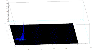
The x-axis corresponds to the R channel, the y-axis corresponds to the G channel and the z axis corresponds to the frequency. From the figure, it can be seen that the region where the frequency is highest is at the blue region as expected.

The following are the results of the color segmentation:

It can be seen from the images that parametric segmentation looks better as it was able to approximate the general shape of the blue parts of the lamp are well separated from the other colors. However, the non-parametric segmentation is very accurate in the sense that slight changes in the shade of blue in the image is no longer considered blue. This is easily observed in the post of the lamp since in this part the shade is darker than the top parts.

----------------------------------------------------------------------------------------------
----------------------------------------------------------------------------------------------
Scilab Codes:
Parametric
I = imread("lamp_section.jpg");
orig = imread("lamp_orig.jpg");
av = I(:,:,1)+I(:,:,2)+I(:,:,3);
r = I(:,:,1)./av;
g = I(:,:,2)./av;
b = I(:,:,3)./av;

av2 = orig(:,:,1)+orig(:,:,2)+orig(:,:,3);
r2 = orig(:,:,1)./av2;
g2 = orig(:,:,2)./av2;
b2 = orig(:,:,3)./av2;

r = r*255;
g = g*255;
frequency = zeros(256,256);
sizer = size(r);
for i=1:sizer(1)
for j=1:sizer(2)
x = abs(round(r(i,j)))+1;
y = abs(round(g(i,j)))+1;
frequency(x,y) = frequency(x,y)+1;
end
end
//imshow(log(frequency+0.0000000001));

r = r/255;
g = r/255;

mr = mean(r);
devr = stdev(r);
mg = mean(g);
devg = stdev(g);

pr = (1/(devr*sqrt(2*%pi)))*exp(-((r2-mr).^2)/2*devr);
pg = (1/(devg*sqrt(2*%pi)))*exp(-((g2-mg).^2)/2*devg);

prob = pr.*pg;
prob = prob/max(prob);
scf(0);imshow(orig);
scf(1);imshow(prob,[]);
-------------------------------------------------------------------------------------------------
Non Parametric:
I = imread("lamp_section.jpg");
orig = imread("lamp_orig.jpg");
sizeO = size(orig)
av = I(:,:,1)+I(:,:,2)+I(:,:,3);
r = I(:,:,1)./av;
g = I(:,:,2)./av;
b = I(:,:,3)./av;

av2 = orig(:,:,1)+orig(:,:,2)+orig(:,:,3);
r2 = orig(:,:,1)./av2;
g2 = orig(:,:,2)./av2;
b2 = orig(:,:,3)./av2;

r = r*255;
g = g*255;
frequency = zeros(256,256);
sizer = size(r);
for i=1:sizer(1)
for j=1:sizer(2)
x = abs(round(r(i,j)))+1;
y = round(g(i,j))+1;
frequency(x,y) = frequency(x,y)+1;
end
end
scf(0);imshow(log(frequency+0.0000000001));

r2 = r2*255;
g2 = g2*255;
seg = zeros(sizeO(1),sizeO(2));
sizer2 = size(r2);

for i = 1:sizer2(1)
for j = 1:sizer2(2)
x = abs(round(r2(i,j)))+1;
y = round(g2(i,j))+1;
seg(i,j) = frequency(x,y);
end
end

scf(1);imshow(log(seg+0.000000000001),[]);
scf(2);imshow(orig);
-------------------------------------------------------------------------------------------------
-------------------------------------------------------------------------------------------------

I will give myself a grade of 10 for this activity since the objectives were met and the results are interesting.
Collaborator:
Ed David

Wednesday, August 27, 2008

Activity 15: Color Image Processing

For this activity, we are to perform 2 different white balancing techniques, called the reference white algorithm and the gray world algorithm. In the reference white algorithm, a reference white object's pixel values are to be used to normalize the red, green and blue channels of the whole image. On the other hand, gray world algorithm uses the mean of each of the RGB channel values as the normalization factor.
We used two sets of objects for this activity. One set is a set of objects with different colors and another set is a set of objects with the same colors. For my second set I used a blue set of objects. The images were taken under a fluorescent lamp using the "tungsten", "daylight" and "cloudy" white balancing settings of a Canon Powershot A460 digital camera.

The following are the results for object with different colors:

TUNGSTEN

CLOUDY

DAYLIGHT

For all the images, Reference white algorithm seems to work better since the gray world algorithm requires a certain constant to be multiplied to reduce the brightness of the resulting image. For this part the constant used to limit the brightness is 0.75.

The following are the results for different blue objects under different white balancing conditions.

CLOUDY


DAYLIGHT


TUNGSTEN

For images with the same color, the reference white algorithm clearly performs better. The results of the gray world algorithm produced images with slightly redder image. A possible reason is because an average of an ensemble of colors may become white but an ensemble of objects having similar colors is not necessarily white. Hence, the white reference algorithm is expected to perform better.

Scilab Code:
I = imread("IMG_0921_cloudy.jpg");

//start of reference white algorithm
imshow(I);
pos = locate(1);
Rw = I(pos(1),pos(2),1);
Gw = I(pos(1),pos(2),2);
Bw = I(pos(1),pos(2),3);

//Start of gray world algorithm
//Rw = mean(I(:,:,1));
//Gw = mean(I(:,:,2));
//Bw = mean(I(:,:,3));

I(:,:,1) = I(:,:,1)/Rw;
I(:,:,2) = I(:,:,2)/Gw;
I(:,:,3) = I(:,:,3)/Bw;
//I = I*0.5;
I(I>1) = 1;

imwrite(I,"enhanced_cloudy.jpg");
----------------------------------------------

10/10 for this activity since I was able to finish the activity quickly and correctly.
Collaborator: Eduardo David


Activity 14: Stereometry

Wednesday, August 6, 2008

Activity 13: Photometric Stereo

In this activity we are to reconstruct an image using different images taken from the same point with different point source locations. The following are the images used with their corresponding point source positions


Using the following formula, we were able to obtain a 3d plot for the original image


loadmatfile("Photos.mat");
scf(0);imshow(I1,[]);
scf(1);imshow(I2,[]);
scf(2);imshow(I3,[]);
scf(3);imshow(I4,[]);
V1 = [0.085832, 0.17365, 0.98106];
V2 = [0.085832, -0.17365, 0.98106];
V3 = [0.17365, 0, 0.98481];
V4 = [0.16318, -0.34202, 0.92542];

I(1,:) = I1(:)';
I(2,:) = I2(:)';
I(3,:) = I3(:)';
I(4,:) = I4(:)';
//I = cat(1,I1(:)',I2(:)',I3(:)',I4(:)');
V = cat(1,V1,V2,V3,V4);

g = inv(V'*V)*V'*I;
N = size(g);

for i = 1:N(2)
gMag(i) = sqrt(g(1,i)**2+g(2,i)**2+g(3,i)**2+0.0000000000001);
end

nh(1,:) = (g(1,:)./gMag');
nh(2,:) = (g(2,:)./gMag');
nh(3,:) = (g(3,:)./gMag')+0.0000000000001;

fx = -nh(1,:)./nh(3,:);
fx = matrix(fx,[128,128])
fy = -nh(2,:)./nh(3,:);
fy = matrix(fy,[128,128]);
f = cumsum(fx,2)+cumsum(fy,1);

plot3d(1:128,1:128,f);


I will grade myself 10 for this activity since I was able to meet the objectives.
Collaborator: Eduardo David

Activity 12

Wednesday, July 30, 2008

Activity 11: Camera Calibration

In this activity, we are to obtain transformation of the camera coordinates with real world coordinates using a checkerboard pattern shown below as a calibration object
I assigned the bottom center of the image as my origin and the left part as the "x" axis and the right part as the "y" and the vertical direction as the "z". To calibrate the camera, first, we assigned 25 corner points chosen at random in the image (marked with yellow squares). The location of the points are obtained using the "locate" function of scilab.
To solve for the camera parameters, we use the following matrix:
Where xo, yo and zo correspond to real world coordinates and yi and zi correspond to image coordinates. aij correspond to the camera parameters.
The camera parameter matrix can be solved using:
Where Q is the matrix containing the real world coordinates and d is the matrix containing the image coordinates.
The camera parameters obtained are as follows:
-19.19404
9.7237133
-0.5773294
167.80985
-2.5034951
-3.831655
20.477795
32.311712
-0.0067168
-0.0120008
-0.0025509

To confirm if this camera parameters are correct, we use it to predict the locations of the selected points in the image from the real world coordinates. The following equation is applied:

Using the above equations I obtained the following results:
The 1st pair of data correspond to the actual image coordinates, 2nd pair correspond to the coordinates solved using the above equation and the 3rd pair corresponds to their difference.


Image Coordinates Solved Coordinates difference
yi zi yi zi yi zi
29.096045 259.60452 29.300782 259.52771 0.204737 0.07681
89.548023 262.42938 89.604812 261.94118 0.056789 0.4882
216.66667 261.86441 216.84828 262.18338 0.18161 0.31897
166.38418 243.22034 166.27818 243.29594 0.106 0.0756
50 214.97175 50.653965 215.20451 0.653965 0.23276
147.74011 220.62147 147.806 220.65636 0.06589 0.03489
217.23164 216.66667 216.9003 216.65975 0.33134 0.00692
91.242938 194.63277 90.702993 195.35542 0.539945 0.72265
229.66102 192.37288 230.33101 192.45105 0.66999 0.07817
31.920904 169.20904 31.45059 169.10213 0.470314 0.10691
147.74011 176.55367 148.21666 177.51489 0.47655 0.96122
191.24294 175.9887 191.22007 175.33202 0.02287 0.65668
129.66102 155.08475 129.68482 154.61499 0.0238 0.46976
73.163842 127.9661 72.303439 128.12011 0.860403 0.15401
167.51412 137.00565 167.05391 136.44094 0.46021 0.56471
204.80226 130.22599 204.04286 129.52077 0.7594 0.70522
258.47458 119.49153 257.94833 119.43573 0.52625 0.0558
33.050847 81.073446 33.55399 80.628618 0.503143 0.444828
129.66102 90.677966 130.44029 90.649574 0.77927 0.028392
191.24294 88.983051 191.58995 88.895726 0.34701 0.087325
92.937853 65.254237 92.847265 65.342247 0.090588 0.08801
217.23164 60.169492 217.07798 61.190191 0.15366 1.020699
34.745763 37.00565 34.588753 37.10424 0.15701 0.09859
149.43503 50.564972 149.42329 50.756407 0.01174 0.191435
243.22034 32.485876 243.74758 32.200294 0.52724 0.285582

The average value of the difference is 0.359 with standard deviation of 0.318. This translates to an error of roughly 1%.

The scilab code I used is given below:
---------------------------------------------------------------------------------
I = imread("C:\Users\RAFAEL JACULBIA\Documents\subjects\186\activity11\marked.bmp");
I = im2gray(I);
//imshow(I,[]);
//d = [];
//d = locate(25,flag=1);

image = [7 4 0 0 6 1 0 4 0 7 1 0 2 5 0 0 0 7 2 0 4 0 7 1 0;
0 0 4 0 0 0 4 0 5 0 0 2 0 0 0 3 7 0 0 2 0 4 0 0 6;
11 11 11 10 9 9 9 8 8 7 7 7 6 5 5 5 5 3 3 3 2 2 1 1 1];


//image = image*72;

Q = [];
yi = [];
zi = [];
for i = 1:25
x = image(1,i);
y = image(2,i);
z = image(3,i);
yi = d(1,i);
zi = d(2,i);
Qi = [x y z 1 0 0 0 0 -(yi*x) -(yi*y) -(yi*z); 0 0 0 0 x y z 1 -(zi*x) -(zi*y) -(zi*z)];
Q = cat(1, Q, Qi);
end
d2 = [];
d2 = matrix(d, 50,1);
a = inv(Q'*Q)*Q'*d2;

for j = 1:25
yi2(j) = ((a(1)*image(1,j))+(a(2)*image(2,j))+(a(3)*image(3,j))+a(4))/((a(9)*image(1,j))+(a(10)*image(2,j))+(a(11)*image(3,j))+1);
zi2(j) = ((a(5)*image(1,j))+(a(6)*image(2,j))+(a(7)*image(3,j))+a(8))/((a(9)*image(1,j))+(a(10)*image(2,j))+(a(11)*image(3,j))+1);
end

for k = 1:25
yi(k) = d(1,k);
zi(k) = d(2,k);
end

tryx = 0;
tryy = 6;
tryz = 1;

yiTry = ((a(1)*tryx)+(a(2)*tryy)+(a(3)*tryz)+a(4))/((a(9)*tryx)+(a(10)*tryy)+(a(11)*tryz)+1)
ziTry = ((a(5)*tryx)+(a(6)*tryy)+(a(7)*tryz)+a(8))/((a(9)*tryx)+(a(10)*tryy)+(a(11)*tryz)+1)
-------------------------------------------------------------------------------------------

For this activity I will give myself a grade of 10 because I was able to obtain quite accurate results.
Thanks to Eduardo David for teaching me how to resize a matrix in scilab